U-Tube Heat Exchanger Manufacturing Guide: Design, Materials, Fabrication, Inspection and Supplier Selection
A Practical Engineering Guide for Chemical, Petrochemical and Process Plants
When a chemical or petrochemical plant needs a shell-and-tube heat exchanger for high-temperature service, significant temperature differences, thermal cycling, or difficult operating conditions, the choice of tube-bundle configuration can have a major impact on equipment reliability, maintenance strategy, and total project cost.
Among the major shell-and-tube configurations, the U-tube heat exchanger is particularly valuable because its tube bundle can accommodate thermal expansion without requiring a conventional floating tube-sheet arrangement.
However, selecting a U-tube heat exchanger is not simply a matter of bending tubes into a U shape.
The real engineering challenge lies in coordinating:
Thermal design
Tube-side and shell-side flow
Tube material
Tube bending
Tube-sheet design
Baffle arrangement
Vibration control
Welding and fabrication
Dimensional tolerances
Inspection and testing
Maintenance access
Transportation and installation
For EPC contractors, plant owners and industrial equipment buyers, the critical question is therefore not simply:
"Can a manufacturer make a U-tube heat exchanger?"
The more important question is:
"Can the manufacturer control the entire engineering and fabrication chain so that the finished exchanger performs reliably under actual plant conditions?"
This guide explains the key considerations when designing, manufacturing and purchasing a U-tube heat exchanger.
1. What Is a U-Tube Heat Exchanger?
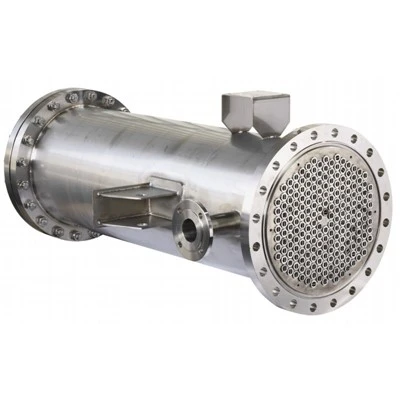
A U-tube heat exchanger is a shell-and-tube heat exchanger in which the heat-transfer tubes are bent into a U-shaped configuration.
Both ends of each tube are connected to the same tube sheet. The tube bundle is installed inside the shell, while the channel or bonnet directs the process fluid into one side of the tube bundle and receives it after the fluid passes through the U-shaped tubes.
The basic flow arrangement is:
Tube-side inlet → straight tube section → U-bend → return tube section → tube-side outlet
Meanwhile, the second process stream flows through the shell side around the tubes.
This configuration creates an important mechanical advantage.
Because the tubes are free to expand and contract along their length, the U-bend can absorb differential thermal expansion between the tube bundle and shell.
This makes U-tube construction particularly attractive for applications involving:
High operating temperatures
Large temperature differences between shell and tube sides
Frequent heating and cooling cycles
Thermal shock
Steam heating
Process cooling
Condensation
Reboiling
High-temperature chemical processing
Petrochemical services
U-tube heat exchangers are therefore not simply an alternative to fixed-tubesheet exchangers. They solve a specific mechanical problem: thermal expansion management.
2. Why Choose a U-Tube Heat Exchanger?
The most important reason for selecting a U-tube design is thermal expansion.
Consider a process exchanger where the tube-side fluid operates at a substantially different temperature from the shell-side fluid.
The tube material and shell material will expand at different rates.
If both ends of straight tubes are rigidly fixed to the shell through stationary tube sheets, thermal expansion can generate substantial stresses.
A U-tube configuration provides a degree of flexibility.
The tube can expand primarily along its axial direction, while the U-bend accommodates movement.
This can significantly simplify the mechanical design of equipment exposed to large temperature differences.
Key advantages include:
2.1 Excellent thermal expansion capability
The U-bend acts as a natural expansion mechanism.
This makes the configuration particularly useful when:
Tube-side temperature is high
Shell-side temperature is relatively low
Start-up and shutdown create thermal cycling
The temperature difference changes significantly during operation
2.2 No conventional floating tube sheet
Unlike a floating-head exchanger, the U-tube configuration does not require a conventional floating tube sheet to accommodate thermal movement.
This can reduce mechanical complexity in some applications.
2.3 Removable tube bundle
The complete U-tube bundle can generally be removed from the shell for inspection and maintenance, provided the equipment layout includes adequate bundle-removal space.
This point is often overlooked during procurement.
A theoretically maintainable heat exchanger may become difficult to service if the plant layout does not provide enough extraction space.
2.4 Good suitability for high-temperature service
The configuration is frequently considered for high-temperature services where differential thermal expansion would be problematic for a fixed-tubesheet arrangement.
2.5 Potentially lower maintenance complexity
With fewer components associated with a conventional floating-head design, the mechanical arrangement can be relatively straightforward.
However, this does not mean that every U-tube exchanger is automatically easier to maintain.
The U-bend itself introduces unique inspection and cleaning considerations.
That distinction is important.
3. U-Tube vs Fixed-Tubesheet vs Floating-Head Heat Exchangers
A common purchasing mistake is to compare heat exchangers only by purchase price.
The better approach is to compare the mechanical configuration against the process conditions.
|
Configuration |
Thermal Expansion |
Tube Bundle Removal |
Tube-Side Cleaning |
Mechanical Complexity |
|---|---|---|---|---|
|
Fixed Tubesheet |
Limited |
Usually difficult |
Good depending on arrangement |
Lower |
|
U-Tube |
Excellent |
Yes |
Straight sections easier; U-bends more difficult |
Moderate |
|
Floating Head |
Excellent |
Yes |
Generally very good |
Higher |
Fixed-Tubesheet Heat Exchanger
A fixed-tubesheet exchanger is attractive when the temperature difference is manageable and shell-side cleaning requirements are acceptable.
It can provide a relatively compact and economical solution.
However, significant differential expansion can become a mechanical design issue.
Floating-Head Heat Exchanger
Floating-head construction provides excellent thermal flexibility and tube-bundle accessibility.
It is often attractive when frequent shell-side cleaning or complete tube access is important.
The trade-off is greater mechanical complexity and potentially higher fabrication and maintenance cost.
U-Tube Heat Exchanger
U-tube construction occupies an interesting middle ground.
It provides excellent thermal expansion capability while maintaining a removable bundle.
For many high-temperature applications, this makes it a practical engineering choice.
4. The First Engineering Decision: Is U-Tube Really the Right Configuration?
One of the most important insights for equipment buyers is this:
Do not start by asking a manufacturer for a U-tube exchanger. Start by defining the process problem.
The appropriate exchanger configuration should be determined from the operating conditions.
A proper preliminary specification should include:
Heat duty
Hot-side inlet temperature
Hot-side outlet temperature
Cold-side inlet temperature
Cold-side outlet temperature
Flow rate
Operating pressure
Design pressure
Operating temperature
Design temperature
Fluid composition
Fluid viscosity
Density
Specific heat
Thermal conductivity
Fouling tendency
Corrosion characteristics
Allowable pressure drop
Cleaning requirements
Design code
Material requirements
Installation restrictions
Only after these parameters are understood should the engineer determine whether U-tube construction provides a meaningful advantage.
This process-first approach is also how GYRO approaches customized process equipment projects: equipment is developed around operating conditions, process requirements, materials, pressure and temperature parameters, dimensions and site conditions rather than treating industrial equipment as an off-the-shelf product.
5. Thermal Design of a U-Tube Heat Exchanger
The thermal performance of an exchanger is determined by the relationship between heat duty, temperature driving force and overall heat-transfer coefficient.
A simplified heat-transfer relationship is:
Q = U × A × ΔTₗₘ
Where:
Q = required heat duty
U = overall heat-transfer coefficient
A = effective heat-transfer area
ΔTₗₘ = log mean temperature difference
In real industrial applications, however, the design is much more complicated.
The engineer must consider:
Tube-side heat transfer
Shell-side heat transfer
Tube-wall resistance
Fouling resistance
Fluid properties
Flow regime
Baffle arrangement
Tube layout
Temperature correction factors
Pressure drop
A larger exchanger is not necessarily a better exchanger.
Increasing heat-transfer area can increase equipment cost, weight and footprint.
Increasing velocity may improve heat transfer but also increase pressure drop and erosion risk.
Reducing pressure drop may require larger flow passages, which can reduce heat-transfer performance.
Therefore, the real design objective is not:
"Maximum heat transfer."
It is:
"Required heat transfer at an acceptable combination of pressure drop, reliability, fabrication cost and operating cost."
This is one of the most important principles when evaluating a custom heat exchanger manufacturer.
6. Tube Diameter and Tube Length
Tube geometry strongly influences both thermal and mechanical performance.
Common design considerations include:
Tube outside diameter
Tube wall thickness
Tube length
Tube pitch
Tube arrangement
Number of tube passes
Tube material
U-bend radius
A smaller tube diameter can provide a higher heat-transfer coefficient under suitable conditions.
However, smaller tubes can also increase pressure drop and may be more difficult to clean.
Longer tubes increase heat-transfer area but can increase exchanger length and transportation difficulty.
For U-tube exchangers, tube length also influences the geometry of the bundle and the required U-bend radius.
This is why tube geometry should not be selected independently from manufacturing capability.
7. The U-Bend Is One of the Most Critical Manufacturing Areas
The U-bend is the defining feature of this exchanger type.
It is also one of the areas where manufacturing quality can strongly influence long-term reliability.
During tube bending, engineers must consider:
Minimum bending radius
Tube wall thickness
Material ductility
Ovality
Wall thinning
Local deformation
Residual stress
Bend-to-bend consistency
Poorly controlled bending can produce local thinning or excessive deformation.
This can reduce the mechanical margin of the tube and create difficulties during inspection or service.
A professional U-tube heat exchanger manufacturer therefore needs more than general pressure-vessel fabrication capability.
The manufacturer must have an appropriate tube-bending process and quality-control system capable of maintaining repeatable geometry.
8. Why Tube Material Selection Matters
The tube is the primary heat-transfer surface.
It is also often the component most exposed to corrosion, erosion and temperature.
Material selection should therefore be based on actual process chemistry rather than simply selecting a commonly used stainless steel.
Depending on service conditions, tube materials may include:
Carbon steel
Stainless steel
Nickel alloys
Duplex stainless steels
Other corrosion-resistant alloys
GYRO works with carbon steel, stainless steel, nickel alloy and duplex materials for customized industrial equipment applications.
For corrosive chemical services, the correct material may have a much larger impact on equipment lifecycle cost than the initial purchase price.
A cheaper material that requires frequent tube replacement may ultimately be much more expensive.
9. Tube-Sheet Design: The Connection Between Thermal and Mechanical Engineering
The tube sheet connects the tube bundle to the exchanger's pressure boundary.
It must withstand:
Tube-side pressure
Shell-side pressure
Differential pressure
Tube-to-tubesheet loads
Thermal effects
External loads
Fabrication stresses
The tube sheet also determines how tubes are arranged and connected.
Possible tube-to-tubesheet joining methods may include:
Tube expansion
Welding
Expansion plus seal welding
Other project-specific joining configurations
The correct approach depends on:
Pressure
Temperature
Fluid toxicity
Leakage requirements
Material combination
Design code
Client specification
For demanding petrochemical services, tube-sheet design should therefore be treated as a critical engineering decision rather than a simple fabrication detail.
10. Baffle Design Is About More Than Supporting Tubes
Baffles perform several functions.
They can:
Support tubes
Direct shell-side flow
Increase turbulence
Improve heat transfer
Reduce unsupported tube span
Help control tube vibration
However, excessive shell-side turbulence can increase pressure drop.
Insufficient support can increase the risk of tube vibration.
Therefore, baffle spacing represents another engineering compromise.
A good exchanger design balances:
Heat transfer + pressure drop + tube support + vibration control + manufacturability.
This is where thermal and mechanical design need to work together.
11. Tube Vibration: A Frequently Underestimated Risk
Tube vibration can result from shell-side flow.
If flow-induced vibration becomes severe, it may eventually lead to:
Tube fretting
Wear
Fatigue damage
Tube-to-baffle contact damage
Leakage
Premature exchanger failure
The risk depends on:
Flow velocity
Tube span
Tube diameter
Tube stiffness
Baffle spacing
Fluid density
Flow pattern
Operating conditions
Therefore, tube support should be evaluated during design rather than added as an afterthought.
For critical petrochemical applications, vibration analysis may become an important part of the engineering review.
12. Shell-Side and Tube-Side Pressure Drop
Heat transfer performance cannot be evaluated independently of pressure drop.
A process engineer may want higher velocity because it can improve heat transfer.
The plant operator, however, may have a strict pressure-drop limit.
Excessive pressure drop can increase pumping or compression requirements.
Therefore, exchanger design should establish allowable pressure drop early in the project.
Typical engineering questions include:
What is the maximum allowable tube-side pressure drop?
What is the maximum allowable shell-side pressure drop?
Is the exchanger installed upstream or downstream of a compressor?
Is the process pump already operating near its pressure limit?
Will fouling increase pressure drop over time?
Is the exchanger operating under vacuum?
These questions can materially change the optimum exchanger design.
13. Fouling Should Be Designed for, Not Discovered Later
Heat exchangers rarely operate under laboratory conditions.
Industrial fluids can contain:
Solids
Heavy hydrocarbons
Salts
Polymerizable materials
Corrosion products
Catalyst fines
Suspended particles
Fouling increases thermal resistance.
As fouling increases, the effective heat-transfer coefficient decreases.
The exchanger may then fail to achieve the required outlet temperature even though the equipment was originally correctly sized.
This is why fouling resistance should be considered during thermal design.
For difficult services, buyers should also ask:
How will the U-tube bundle actually be cleaned after several years of operation?
This is one of the key differences between a theoretical design and a practical industrial design.
14. The Cleaning Challenge of U-Tube Heat Exchangers
U-tube construction has a major advantage in thermal expansion.
But it also has a practical limitation:
The curved section is more difficult to mechanically clean than a straight tube.
This becomes particularly important when the process fluid contains deposits.
Before choosing U-tube construction, engineers should determine:
Whether mechanical tube cleaning is required
Whether chemical cleaning is acceptable
Whether the process is prone to fouling
Whether inspection of the U-bend region is necessary
Whether the tube bundle can be removed from the shell
Whether sufficient maintenance space exists
Therefore, U-tube design is particularly attractive when thermal expansion is a dominant concern and the service does not create unacceptable cleaning limitations.
15. Manufacturing Process for U-Tube Heat Exchangers
A high-quality U-tube heat exchanger should be manufactured through a controlled sequence rather than simply assembled from purchased components.
A typical manufacturing workflow includes:
Step 1 - Technical clarification
The manufacturer reviews:
Process datasheet
Equipment specification
Design conditions
Materials
Applicable codes
Client standards
Inspection requirements
Delivery requirements
Step 2 - Thermal and mechanical design
The design team develops:
Heat-transfer area
Tube diameter
Tube length
Tube count
Tube passes
Shell diameter
Baffle arrangement
Tube-sheet configuration
Nozzle arrangement
Support arrangement
Step 3 - Material procurement
Materials are purchased according to approved specifications.
Material identification and traceability are important, particularly for pressure-retaining components and corrosion-resistant alloys.
Step 4 - Shell fabrication
Shell sections are:
Cut
Formed
Welded
Aligned
Inspected
Step 5 - Tube-sheet fabrication
Tube sheets require precise machining.
Tube-hole location, diameter, pitch and positional accuracy directly influence tube-bundle assembly.
Step 6 - Tube preparation and bending
Straight tubes are cut and prepared before being formed into U-shapes.
The bending process should control:
Radius
Ovality
Wall thinning
Bend geometry
Dimensional consistency
Step 7 - Tube-bundle assembly
The tubes are installed into the tube sheet and supported by the baffle system.
Step 8 - Tube-to-tubesheet joining
The selected joining method is applied according to the approved engineering specification.
Step 9 - Shell and bundle assembly
The tube bundle is inserted into the shell.
Clearance and alignment must be verified.
Step 10 - Welding and nozzle installation
Process nozzles, supports, lifting lugs and other attachments are installed.
Step 11 - Inspection and testing
The exchanger is subjected to the specified inspection and pressure/leak testing program.
Step 12 - Final dimensional inspection
Critical dimensions are checked against approved drawings.
Step 13 - Surface treatment and preservation
The equipment is cleaned, treated and prepared for transportation according to project requirements.
Step 14 - Packing and delivery
Large heat exchangers require transportation planning from the beginning of fabrication.
16. Welding Quality Is a Major Part of Heat Exchanger Reliability
A heat exchanger is not only a thermal device.
It is also a pressure-containing piece of industrial equipment.
Welding therefore plays a major role in reliability.
Important welding controls include:
Qualified welding procedures
Qualified welders
Material traceability
Preheating where required
Interpass temperature control
Welding consumable control
Post-weld heat treatment where required
Weld inspection
Dimensional inspection
GYRO currently has certified welders covering 36 qualified welding items, supported by qualified NDT personnel covering RT, UT, MT and PT inspection activities.
This capability is particularly relevant for customized petrochemical equipment where fabrication quality can be as important as the original thermal design.
17. NDT and Inspection of U-Tube Heat Exchangers
Inspection requirements depend on design code, service conditions, client specifications and equipment classification.
Potential inspection methods include:
Visual Inspection
Used to examine:
Weld appearance
Surface defects
Assembly quality
Tube-sheet condition
Nozzle alignment
General workmanship
Radiographic Testing - RT
Used where radiographic examination is specified for weld quality assessment.
Ultrasonic Testing - UT
Can be used for weld and material examination depending on the inspection plan.
Magnetic Particle Testing - MT
Useful for detecting surface and near-surface discontinuities in suitable ferromagnetic materials.
Penetrant Testing - PT
Useful for detecting surface-breaking defects, particularly on non-ferromagnetic materials.
Pressure Testing
The pressure boundary may be tested according to the applicable design code and project specification.
Tube-Side Leak Testing
Depending on design and service requirements, additional leak-testing methods may be specified.
A professional manufacturer should be able to provide a clear inspection and test plan rather than simply stating that the exchanger is "tested."
18. Dimensional Accuracy Matters More Than Many Buyers Expect
Heat exchanger performance depends on many components being assembled correctly.
Dimensional problems can create:
Tube installation difficulties
Nozzle misalignment
Bundle insertion problems
Piping connection problems
Support installation problems
Excessive stress during field installation
Important dimensions may include:
Overall length
Shell diameter
Nozzle orientation
Nozzle projection
Support location
Tube-sheet dimensions
Bundle dimensions
U-bend geometry
Flange dimensions
For large industrial equipment, dimensional inspection should be part of the manufacturing quality plan.
19. How GYRO Approaches Custom U-Tube Heat Exchanger Manufacturing
GYRO is not positioned only as a standard equipment reseller.
The company's manufacturing and engineering model is centered on customized chemical and petrochemical equipment.
GYRO's manufacturing operations date back to 2002, while its design company was established in 2016.
The current facility covers approximately 30,000 m², including approximately 20,000 m² of workshop area.
The company reports:
50+ design professionals
68 manufacturing personnel
15 engineering and technical personnel
8,000+ tons of annual designed production capacity
150+ manufacturing and processing equipment units
14 certified welders
4 qualified NDT personnel
GYRO also holds an A2-level Pressure Vessel Design and Manufacturing License issued by the Shandong Provincial Administration for Market Regulation.
These capabilities are important because large custom heat exchangers require coordination among engineering, fabrication, quality control and project management.
The company's equipment portfolio includes:
Heat Exchanger
Shell and Tube Heat Exchanger
as well as:
Stainless Steel Reactor
Glass Lined Reactor
Fired Heater
This broader manufacturing capability allows a heat exchanger project to be evaluated within the context of the complete chemical process rather than as an isolated piece of equipment.
20. Why a Heat Exchanger Manufacturer's Broader Manufacturing Capability Matters
A chemical plant rarely buys only one piece of equipment.
An EPC project may require:
Reactors
Heat exchangers
Towers
Pressure vessels
Fired heaters
Storage equipment
Skids
Auxiliary equipment
The interfaces between these pieces of equipment can affect the success of the overall project.
For example:
A reactor may discharge a hot process stream.
That stream may enter a heat exchanger.
The cooled stream may then enter a tower.
The tower may require additional heating or cooling.
The final equipment arrangement must therefore be considered as a process system.
This is one reason GYRO emphasizes engineering, fabrication, inspection, installation, maintenance and modification rather than simply supplying individual equipment items.
21. What Makes a Good U-Tube Heat Exchanger Manufacturer?
When comparing suppliers, buyers should look beyond the quotation price.
A useful supplier evaluation framework includes five areas.
21.1 Engineering Capability
Ask:
Can the supplier review process conditions?
Can they perform thermal and mechanical design?
Can they work from customer drawings?
Can they handle non-standard designs?
Can they adapt the exchanger to site restrictions?
21.2 Fabrication Capability
Ask:
What is the workshop size?
What is the annual production capacity?
Can they handle large shells?
Can they fabricate tube sheets?
Can they perform precision machining?
Can they manufacture U-tube bundles?
21.3 Quality Control
Ask:
Are welders qualified?
What NDT capabilities are available?
How is material traceability controlled?
What inspection documentation is provided?
What pressure testing is included?
21.4 Project Management
Ask:
Who is responsible for technical clarification?
How are drawing revisions controlled?
How are inspection points coordinated?
How is delivery managed?
Can the supplier support installation?
21.5 Lifecycle Support
Ask:
Can the manufacturer provide replacement tubes?
Can they support maintenance?
Can they modify existing equipment?
Can they help troubleshoot performance issues?
This final category is often ignored during purchasing but can become very important several years after commissioning.
22. The Most Common U-Tube Heat Exchanger Purchasing Mistakes
Mistake 1: Buying Based Only on Price
A low initial quotation does not necessarily mean low lifecycle cost.
Material, inspection, engineering, spare parts and maintenance can significantly affect total ownership cost.
Mistake 2: Ignoring Cleaning Requirements
The U-bend can create cleaning limitations.
The process should therefore be evaluated before the configuration is finalized.
Mistake 3: Providing Insufficient Process Data
A manufacturer cannot responsibly optimize the exchanger without sufficient process information.
Mistake 4: Treating Thermal Design and Mechanical Design Separately
A thermally efficient exchanger may create excessive pressure drop or mechanical problems.
Mistake 5: Ignoring Transportation
Large heat exchangers can create transportation restrictions involving:
Length
Diameter
Weight
Route limitations
Crane capacity
Site access
Transportation should be considered during equipment design.
Mistake 6: Not Planning Bundle Removal
A removable tube bundle is only useful if the plant can actually remove it.
Maintenance space should therefore be considered during layout design.
23. What Information Should You Send to a U-Tube Heat Exchanger Manufacturer?
If you want a meaningful quotation rather than a rough budgetary number, provide as much of the following information as possible:
Process Data
Fluid name
Fluid composition
Flow rate
Inlet temperature
Outlet temperature
Operating pressure
Design pressure
Operating temperature
Design temperature
Thermal Data
Required heat duty
Heat-transfer coefficient if available
Fouling resistance
Allowable pressure drop
Heat-transfer area if already specified
Mechanical Data
Design code
Material requirements
Corrosion allowance
Tube specification
Shell specification
Tube-sheet material
Insulation requirements
Project Data
Equipment dimensions
Weight limitation
Site conditions
Nozzle orientation
Maintenance clearance
Transportation limitations
Quality Requirements
Inspection standard
NDT requirements
Pressure testing requirements
Third-party inspection requirements
Documentation requirements
Certification requirements
The more complete the technical package, the more accurately a manufacturer can evaluate the project.
24. A Practical U-Tube Heat Exchanger RFQ Checklist
Before sending an RFQ, the buyer should ideally prepare:
☐ Process datasheet
☐ Heat duty
☐ Fluid composition
☐ Flow rates
☐ Operating temperature
☐ Design temperature
☐ Operating pressure
☐ Design pressure
☐ Allowable pressure drop
☐ Fouling information
☐ Material requirements
☐ Design code
☐ Tube specification
☐ Tube-sheet requirements
☐ Inspection requirements
☐ NDT requirements
☐ Pressure-testing requirements
☐ Equipment drawing, if available
☐ Nozzle orientation
☐ Installation restrictions
☐ Transportation restrictions
☐ Required delivery date
If some information is unavailable, a qualified manufacturer should be able to identify the missing parameters rather than simply reject the inquiry.
25. U-Tube Heat Exchanger: Engineering Questions Buyers Should Ask
Before selecting a manufacturer, ask these questions:
Question 1
Why is U-tube construction preferable to fixed tubesheet or floating-head construction for this application?
Question 2
What is the expected thermal expansion between shell and tube bundle?
Question 3
How will the U-bend radius be selected?
Question 4
How will tube wall thinning and ovality during bending be controlled?
Question 5
How will tube vibration be evaluated?
Question 6
What cleaning method is recommended for the U-bend region?
Question 7
What inspection is planned for tube-to-tubesheet connections?
Question 8
How will material traceability be maintained?
Question 9
Can the complete tube bundle be removed at the plant?
Question 10
What documentation will be delivered with the equipment?
These questions quickly distinguish a simple fabricator from a manufacturer capable of supporting an engineered heat-transfer project.
26. Why Customized Manufacturing Can Be Better Than a Standard Catalog Exchanger
Chemical and petrochemical plants rarely operate under identical conditions.
Even two exchangers performing apparently similar duties may have different:
Fluid properties
Pressure requirements
Temperature ranges
Fouling behavior
Corrosion conditions
Installation constraints
Maintenance strategies
Therefore, customized design can provide a better fit than selecting an exchanger from a standard catalog.
GYRO's engineering team can work from:
Customer drawings
Equipment specifications
Process data
Technical datasheets
Project requirements
Existing equipment information
Customized design requirements
This approach is particularly useful for replacement projects, revamps and non-standard process equipment.
27. U-Tube Heat Exchangers for Chemical and Petrochemical Applications
U-tube exchangers can be considered for a broad range of industrial applications, including:
Petrochemical Plants
Process cooling
Feed preheating
Product cooling
Condensation
Heat recovery
Chemical Plants
Reactor feed heating
Product cooling
Solvent heating
Process heat recovery
Condensation
Energy Projects
Steam-related heat transfer
Process heating
Process cooling
Waste-heat recovery
Fine Chemical Plants
Controlled process heating
Batch-process temperature control
Solvent condensation
Product cooling
The final configuration should always be determined from the actual process conditions.
28. The Real Value of a U-Tube Heat Exchanger Is Not the Steel
A heat exchanger is sometimes evaluated primarily by:
Shell diameter
Tube material
Weight
Price
But these parameters do not fully describe equipment value.
The real value lies in whether the exchanger can:
Transfer the required heat → maintain acceptable pressure drop → withstand operating conditions → tolerate thermal cycling → resist corrosion → remain maintainable → operate reliably throughout its intended service life.
This is why experienced industrial buyers evaluate the manufacturer as carefully as the equipment specification.