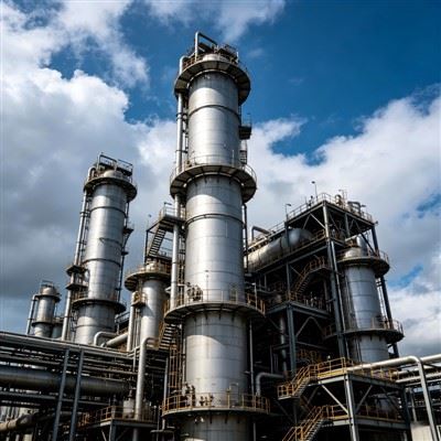
Industrial Steam Generator Selection Guide: Process Design, Equipment Types, Heat Recovery, Manufacturing Challenges, and Industrial Applications
1. Introduction: How to Select the Right Industrial Steam Generator
Steam is one of the most important energy carriers in modern industrial facilities. Refineries, petrochemical complexes, chemical plants, fertilizer factories, power stations, and many manufacturing industries rely on steam for process heating, stripping, distillation, reaction temperature control, equipment cleaning, and mechanical power generation.
An industrial steam generator converts thermal energy into usable steam under controlled pressure, temperature, and flow conditions. Depending on the application, the heat source may be natural gas, fuel oil, process waste heat, gas turbine exhaust, hot process gas, or electricity.
However, selecting an industrial steam generator is more complicated than choosing a boiler with a certain steam capacity. The correct equipment must match the plant's steam demand, operating pressure, steam quality, heat-source characteristics, feedwater conditions, load variation, site limitations, and applicable pressure-equipment regulations.
A poorly selected system can create significant operating and financial problems:
Insufficient steam production during peak process demand.
Unstable steam pressure during load changes.
Excessive fuel consumption and high operating costs.
Poor heat recovery from available process waste streams.
Corrosion, scaling, and tube failure caused by unsuitable water treatment.
Thermal fatigue caused by frequent startup and shutdown.
Inadequate steam separation and excessive moisture carryover.
High maintenance costs due to difficult access to pressure parts.
Fabrication and installation delays caused by incomplete equipment specifications.
For project owners and EPC contractors, the most important question is not simply how much steam a unit can generate. It is how to select a steam-generation system that integrates reliably with the entire production process.
This guide explains the major types of industrial steam generators, process design considerations, heat-recovery options, pressure-part engineering, manufacturing challenges, inspection requirements, and industrial applications. It also explains what buyers should evaluate when selecting a steam-generator manufacturer or equipment supplier.
2. What Is an Industrial Steam Generator?
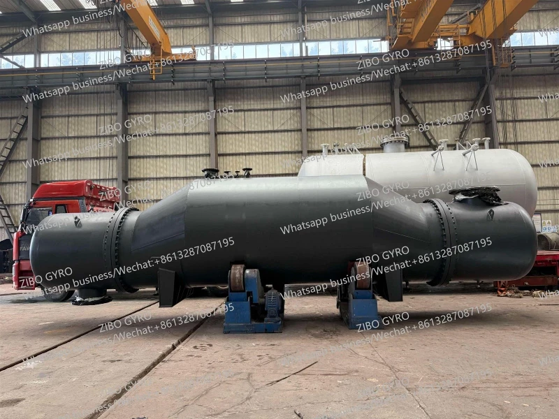
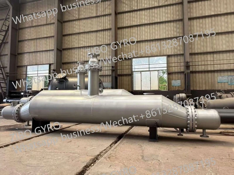
An industrial steam generator is a system that transfers heat to feedwater to produce steam at a specified pressure, temperature, and flow rate.
Depending on the heat source and equipment configuration, the term can refer to several different types of equipment:
Fuel-fired steam boilers.
Waste heat steam generators.
Heat recovery steam generators (HRSGs).
Process gas steam generators.
Once-through steam generators.
Electric steam generators.
Specialized steam-generating equipment integrated with chemical process systems.
These systems share the same basic objective-producing usable steam-but their process arrangements and mechanical structures can be substantially different.
A conventional boiler generally uses a dedicated combustion system or heat source. A waste heat steam generator recovers thermal energy from a hot process stream or exhaust gas. An HRSG is commonly associated with gas turbine exhaust and combined heat and power systems.
The distinction is important because each system requires a different thermal design basis, equipment configuration, control strategy, and manufacturing approach.
3. Main Types of Industrial Steam Generators
The first step in selecting equipment is to identify the appropriate steam-generation technology.
3.1 Fire-Tube Steam Generators
In a fire-tube boiler, hot combustion gases flow through tubes surrounded by water. Heat transfers through the tube walls to the surrounding water, producing steam.
The main characteristics include:
Relatively compact construction for suitable capacities.
A comparatively large water inventory.
Established fabrication and operating principles.
Potentially stable steam supply for relatively steady loads.
Pressure and capacity limitations determined by the specific design.
Fire-tube boilers are commonly used for industrial utilities, manufacturing facilities, commercial heating, and smaller process steam systems.
They may be suitable where steam demand is moderate and operating conditions are relatively stable. However, for very high steam capacities, high pressures, or applications involving specialized heat recovery, a water-tube or other configuration may be more appropriate.
3.2 Water-Tube Steam Generators
In a water-tube steam generator, water and steam flow inside tubes while hot combustion gases or process gases pass around the tubes.
This configuration is widely used for higher-capacity and higher-pressure steam generation.
Typical components include:
Steam drum.
Water-wall tubes, where applicable.
Evaporator tube banks.
Superheater.
Economizer.
Headers and connecting piping.
Feedwater system.
Combustion chamber or hot-gas duct.
Safety and control equipment.
Water-tube designs offer flexibility in arranging heating surfaces and steam-water circuits. They are particularly useful in industrial plants that require substantial steam production or multiple pressure levels.
The mechanical design must account for circulation, tube-wall temperature, pressure-part integrity, thermal expansion, and water chemistry.
3.3 Waste Heat Steam Generators
A waste heat steam generator (WHSG), sometimes called a waste heat recovery boiler (WHRB), uses heat from an existing industrial process stream instead of relying entirely on a dedicated fuel-fired heating system.
Potential heat sources include:
High-temperature process gas.
Furnace exhaust gas.
Refinery flue gas.
Chemical reactor effluent.
Gasification process gas.
Incinerator exhaust.
Hot gases from industrial thermal processes.
A typical system may include an evaporator, steam drum, economizer, superheater, gas inlet and outlet ducts, and associated piping.
The economic advantage is that part of the heat input comes from energy that would otherwise be rejected to the environment.
However, a waste heat steam generator must be designed around the actual heat-source conditions. Gas flow rate, inlet temperature, composition, dust loading, corrosive components, pressure drop, and operating variability all affect equipment selection.
A heat-recovery system is not automatically economical simply because waste heat is available. The recovered energy must be technically usable and must justify the capital, maintenance, and integration costs.
3.4 Heat Recovery Steam Generators (HRSG)
An HRSG is commonly used in combined-cycle power plants and industrial cogeneration systems. It recovers heat from gas turbine exhaust to produce steam.
The steam may be used for:
Process heating.
Steam turbine power generation.
Mechanical drives.
Plant utility networks.
Combined heat and power systems.
A typical HRSG includes several heat-transfer sections:
Economizer: Preheats feedwater before it enters the evaporation section.
Evaporator: Transfers heat to water until it reaches saturation conditions and produces steam.
Steam drum: Separates steam from water in drum-type configurations and provides a water inventory for the circulation system.
Superheater: Raises steam temperature above the saturation temperature when superheated steam is required.
Depending on the project, the HRSG may use one or multiple pressure levels, with optional supplementary firing.
The choice of single-pressure, dual-pressure, or triple-pressure configuration depends on exhaust-gas conditions, steam demand, power-generation requirements, and economic optimization.
The U.S. Department of Energy's CHP guidance describes HRSG systems as heat-recovery equipment using hot exhaust gases to produce steam or hot water, and explains the roles of the economizer, evaporator, and superheater. https://www.energy.gov/sites/default/files/2013/11/f4/chp_boilers_guide.pdf
3.5 Once-Through Steam Generators
A once-through steam generator is designed so that feedwater passes through the heating circuit and is converted into steam without relying on a conventional steam drum for water-steam separation.
The feedwater moves through a sequence of heating regions as it absorbs heat.
Potential advantages include:
Compact pressure-part arrangements.
Reduced or eliminated steam-drum requirements.
Suitability for certain high-pressure applications.
Potentially rapid response under appropriately designed operating conditions.
However, once-through systems have demanding requirements for feedwater quality, flow control, thermal management, and operating flexibility.
They are not automatically a better replacement for conventional drum-type boilers. Their suitability depends on the operating pressure, heat-source characteristics, load profile, control system, and the technology selected.
3.6 Electric Steam Generators
Electric steam generators use electrical resistance or other electrical heating methods to produce steam.
They may be attractive where:
Electricity is readily available.
Local emissions restrictions are stringent.
Steam demand is relatively small or intermittent.
Electrical energy costs are competitive.
The plant needs a supplementary or standby steam source.
For large industrial steam demand, the electricity consumption and overall energy economics must be evaluated carefully.
The best choice depends on the local power mix, energy price, demand profile, and environmental requirements.
4. How to Choose the Right Steam Generator Type
Different steam-generation technologies solve different industrial problems. The correct choice should begin with the available heat source and required steam conditions.
| Selection factor | Fire-tube boiler | Water-tube boiler | Waste heat generator / HRSG | Once-through generator |
|---|---|---|---|---|
| Main heat source | Fuel combustion | Fuel combustion | Process waste heat or exhaust gas | Fuel, electricity, or another designed heat source |
| Typical application | Moderate industrial steam demand | Higher-capacity or higher-pressure steam | Energy recovery and cogeneration | Specialized high-pressure or compact systems |
| Steam drum | Normally used | Common in drum-type designs | Common in conventional HRSG designs | Usually not required |
| Heat-source flexibility | Depends on burner design | Depends on firing arrangement | Depends on process exhaust conditions | Depends on system design |
| Key design concern | Shell and tube pressure integrity | Circulation and tube pressure parts | Heat-source variation and thermal integration | Feedwater control and thermal management |
| Maintenance focus | Internal inspection and tube cleaning | Tube inspection and water chemistry | Fouling, corrosion, and thermal cycling | Flow control and water quality |
This table is a general selection guide. Actual capacity, pressure, temperature, and applicability depend on the approved design and applicable code.
4.1 When should a fuel-fired steam generator be selected?
A fuel-fired unit is generally considered when the plant requires a controllable steam source independent of process waste-heat availability.
It may be suitable for:
New chemical plants without sufficient recoverable waste heat.
Refinery utility systems.
Facilities requiring reliable standby steam.
Plants with variable steam demand.
Sites where suitable fuel is available at competitive cost.
The design should consider fuel characteristics, combustion air, burner turndown, emissions requirements, stack arrangement, and fuel-supply reliability.
4.2 When should a waste heat steam generator be selected?
A waste heat steam generator is attractive when a process produces a sufficiently hot and stable stream that can transfer useful heat to feedwater.
The engineering team should first establish:
Available waste-gas flow rate.
Gas inlet temperature and expected variation.
Gas composition.
Dust and particulate content.
Corrosive components.
Allowable process-side or exhaust-side pressure drop.
Required steam pressure and flow.
Operating hours and production stability.
A waste heat unit should not be sized using only the maximum available gas temperature. The full heat balance must account for gas flow, heat capacity, outlet temperature limitations, fouling, and operating cases.
4.3 When is an HRSG more appropriate?
An HRSG is often the preferred option where a gas turbine or another suitable high-temperature exhaust source is already part of the facility.
The system may produce steam at several pressure levels to serve different process consumers or a steam turbine.
Its selection should be integrated with the gas turbine operating map, exhaust conditions, plant steam balance, power-generation objectives, and overall cogeneration strategy.
4.4 Why the lowest initial purchase price is not always the best option
A low-cost steam generator may have higher fuel consumption, poorer turndown, more difficult maintenance, or limited compatibility with the plant's operating conditions.
A more complete economic evaluation should consider:
Capital investment.
Fuel or electricity consumption.
Recovered heat value.
Feedwater treatment cost.
Auxiliary power.
Maintenance and inspection.
Downtime risk.
Emissions-control requirements.
Equipment lifetime.
Integration and installation cost.
The correct decision is based on total lifecycle cost rather than purchase price alone.
5. Process Design: Define Steam Requirements Before Equipment Selection
The most important input for steam-generator selection is the actual steam demand of the plant.
A system designed for the wrong pressure, temperature, flow rate, or steam quality may be unable to support the downstream process.
5.1 Steam capacity and demand profile
Steam capacity is usually expressed as mass flow rate, such as kg/h or tonnes per hour.
The design should identify:
Normal steam consumption.
Maximum steam consumption.
Minimum operating demand.
Startup demand.
Intermittent or batch-process demand.
Future expansion requirements.
Standby or emergency steam requirements.
For plants with several steam consumers, the engineering team should prepare a steam balance rather than simply adding nominal equipment ratings.
The demand profile may change significantly during startup, regeneration, cleaning, or product changeover.
An oversized steam generator can operate inefficiently at low load, while an undersized system may fail during peak demand.
5.2 Steam pressure selection
Steam pressure affects saturation temperature, heat-transfer driving force, distribution losses, equipment design pressure, and downstream process requirements.
Common industrial steam networks may include:
High-pressure steam.
Medium-pressure steam.
Low-pressure steam.
The exact pressure levels should be determined from the process heat balance and the requirements of the steam users.
For example, a high-temperature reactor heating duty may require a different steam condition from a tank-heating system or a low-temperature stripping application.
Generating steam at unnecessarily high pressure increases pressure-part design requirements and may increase capital cost. Generating it at too low a pressure can reduce its usefulness for downstream processes.
The objective is to select steam pressure levels that meet the process requirements while allowing efficient energy integration.
5.3 Saturated steam versus superheated steam
Saturated steam exists at the saturation temperature corresponding to its pressure. It is widely used for process heating because condensation provides a high and relatively stable heat-transfer coefficient.
Superheated steam is heated above its saturation temperature.
It may be required for:
Steam turbine applications.
Certain high-temperature process duties.
Long distribution systems where moisture formation must be managed.
Specialized chemical processes.
Superheated steam is not automatically preferable for process heating. If the consumer primarily needs latent heat from condensation, saturated steam may be more practical.
The specification should state whether the required steam is saturated or superheated and define the allowable moisture content, temperature, pressure, and delivery conditions.
5.4 Steam quality and moisture control
Steam quality is particularly important for equipment that uses steam directly or relies on consistent heat transfer.
Wet steam may cause:
Reduced usable enthalpy.
Water hammer.
Erosion of valves and fittings.
Unstable control.
Poor heating performance.
Damage to certain downstream equipment.
For drum-type systems, steam separation internals help remove water droplets from the generated steam.
The steam drum may use a combination of gravity separation, baffles, separators, or other internals depending on the design.
The design should also consider the potential for foaming, carryover, and contamination caused by poor feedwater chemistry or unsuitable operating conditions.
5.5 Feedwater quality
Feedwater quality is one of the most important factors determining steam-generator reliability.
Poor feedwater quality can lead to:
Scale formation.
Tube overheating.
Under-deposit corrosion.
Oxygen corrosion.
Foaming and carryover.
Reduced heat-transfer efficiency.
Premature pressure-part failure.
A typical industrial water-treatment system may include filtration, softening, reverse osmosis, demineralization, deaeration, chemical dosing, and blowdown treatment, depending on the required water quality.
The feedwater specification must follow the selected steam-generator technology, pressure level, materials, and applicable water-treatment standard.
A steam generator should never be selected independently of its feedwater preparation and chemical-treatment system.
6. Thermal Design: Turning Available Heat into Useful Steam
The thermal design determines how much steam can be generated from the available heat source and how efficiently the equipment can transfer energy.
6.1 Basic steam-generation heat balance
A simplified heat balance can be expressed as:
Q=ms(hs-hfw)
Where:
Q-- heat transferred to the water-steam system.
ms-- steam production rate.
hs-- specific enthalpy of the generated steam.
hfw--specific enthalpy of feedwater.
This relationship shows why steam production cannot be estimated from heat-source temperature alone.
The available heat duty depends on both the heat-source flow rate and its usable temperature range.
For a waste heat generator, a simplified source-side balance may be written as:
Q=mg cp,g(Tg,in-Tg,out)
Where:
mg-- hot-gas mass flow rate.
Cp,g-- gas specific heat capacity.
Tg,in-- gas inlet temperature.
Tg,out-- gas outlet temperature.
Actual calculations should account for variable gas properties, phase changes, radiation where relevant, fouling, and heat losses.
6.2 Heat-transfer surface area
The required heating surface depends on heat duty, heat-transfer coefficient, and the effective temperature difference.
A simplified relationship is:
Q = U A▲Tlm
Where:
U-- overall heat-transfer coefficient.
A-- heat-transfer area.
Tlm--log-mean temperature difference.
In real steam-generation equipment, the heating surface is divided into different functional sections.
The economizer, evaporator, and superheater operate under different thermal conditions and have different heat-transfer characteristics.
A single overall coefficient should not replace a section-by-section thermal analysis where the equipment configuration requires it.
6.3 Economizer design
The economizer preheats feedwater using relatively low-temperature heat from the flue gas or process exhaust.
Its main purpose is to recover heat that would otherwise leave the system through the stack or exhaust duct.
However, economizer design must consider:
Feedwater inlet temperature.
Water pressure and flow distribution.
Gas-side temperature.
Tube-wall temperature.
Corrosion risk.
Fouling and cleaning.
Gas-side pressure drop.
Thermal expansion.
If sulfur-containing gas is present, the economizer and stack design must account for acid-dew-point corrosion risk. The gas outlet temperature and cold-end metal temperature should be selected with the actual fuel and gas composition in mind.
6.4 Evaporator design
The evaporator is the principal steam-generating section in a conventional drum-type system.
Water absorbs heat and changes phase into a water-steam mixture. The circulation system must maintain adequate flow through the heated tubes to prevent local overheating.
Depending on the configuration, circulation may be natural or forced.
The design should consider:
Circulation ratio.
Heat flux.
Tube diameter and wall thickness.
Flow stability.
Pressure drop.
Local metal temperature.
Steam-water separation.
Startup and low-load behavior.
The evaporator is especially important because poor circulation or inadequate cooling can cause tube overheating and pressure-part damage.
6.5 Superheater design
The superheater raises steam temperature above saturation temperature.
It is commonly located in a hotter region of the gas path, depending on the arrangement.
Important design considerations include:
Required steam outlet temperature.
Steam flow during startup and low-load operation.
Tube metal temperature.
Gas-side temperature distribution.
Attemperation or desuperheating requirements.
Thermal expansion.
Oxidation and high-temperature material performance.
Superheater tubes may experience higher metal temperatures than evaporator tubes, so material selection and temperature control are particularly important.
6.6 Pinch point and approach temperature
For HRSG and waste heat recovery applications, the pinch point is an important thermal design parameter.
It describes the minimum temperature difference between the hot exhaust gas and the boiling water or steam-water mixture in the evaporation section, according to the selected design convention.
A smaller pinch point can allow greater heat recovery, but it may require more heat-transfer surface and increase equipment cost.
Similarly, the economizer approach temperature influences how closely feedwater temperature approaches the saturation temperature.
These values should be optimized together with:
Equipment capital cost.
Exhaust-gas pressure drop.
Steam production.
Stack temperature.
Fouling allowance.
Operating flexibility.
Maintenance requirements.
A design that maximizes heat recovery at one operating point may not provide the best overall result under variable operating conditions.
7. Waste Heat Recovery: An Important Opportunity in Chemical and Petrochemical Plants
Many industrial processes reject large quantities of thermal energy through exhaust gases and hot process streams.
A waste heat steam generator can convert part of this energy into steam for plant use, reducing the need for additional fuel-fired steam generation.
7.1 Typical waste heat sources
Potential heat sources include:
Refinery furnaces: Flue gas from process heaters may provide recoverable heat, subject to temperature, composition, and existing heat-recovery arrangements.
Catalytic cracking units: Certain hot flue-gas streams may be suitable for heat recovery, depending on the process configuration and particulate loading.
Hydrogen production units: Reforming and other high-temperature processes can generate substantial heat streams that may be integrated with steam generation.
Gasification systems: Hot syngas or exhaust streams may offer heat-recovery opportunities, subject to gas cleanliness, corrosion, and process constraints.
Chemical reactors: Exothermic reaction systems may provide useful heat for steam generation through waste heat boilers or process heat exchangers.
Incineration and thermal oxidation: High-temperature exhaust gases may be used to generate steam where gas composition and emissions requirements permit.
7.2 The importance of gas composition
A hot gas stream is not automatically a suitable heat source.
The design team should evaluate:
Dust and particulate loading.
Sulfur compounds.
Chlorides and other corrosive species.
Condensable components.
Gas velocity and distribution.
Fouling tendency.
Erosion potential.
Gas-side pressure drop.
Expected operating variability.
For example, a gas containing significant particulate matter may require wider tube spacing, sootblowing, cleaning access, or another fouling-control arrangement.
A corrosive gas may require special materials or cold-end temperature management.
7.3 Avoid excessive exhaust-side pressure drop
For gas turbine HRSG applications, exhaust-side pressure drop is particularly important because excessive backpressure can adversely affect gas turbine performance.
A larger heat-transfer surface may increase heat recovery, but it may also increase gas-side resistance.
The design should therefore optimize heat recovery and exhaust-system pressure drop together rather than maximizing heat-transfer area without considering the upstream equipment.
7.4 Single-pressure and multi-pressure systems
A single-pressure HRSG generates steam at one main pressure level.
A multi-pressure HRSG produces steam at two or more pressure levels, allowing better matching between exhaust-gas temperature and the steam cycle.
Multi-pressure systems can improve heat recovery in suitable applications, but they add equipment, piping, controls, and operational complexity.
The final decision depends on the heat-source profile, plant steam balance, investment budget, and intended use of the steam.
The Singapore National Environment Agency's industrial energy-efficiency guidance discusses the role of HRSGs and the importance of matching steam pressure levels to the overall energy balance of refinery, petrochemical, and chemical facilities. https://www.nea.gov.sg/docs/default-source/cmd-documents/energy-efficiency/best-practice-guide-for-heating-systems.pdf
8. Mechanical Design: Pressure Parts and Major Equipment Components
A steam generator is not simply a heat exchanger. It is a pressure-containing system operating under elevated temperature and pressure, often with demanding thermal cycling and water-chemistry requirements.
The mechanical design must address the entire pressure boundary and its interaction with the supporting structure, piping, combustion system, and plant layout.
8.1 Steam drum
The steam drum is an important component of many conventional water-tube boilers and HRSGs.
It provides space for steam-water separation and contributes to the water inventory of the system.
Mechanical design considerations include:
Design pressure and temperature.
Shell and head thickness.
Material selection.
Nozzle reinforcement.
Internal separator arrangement.
Water-level instrumentation.
Blowdown connections.
Manholes and inspection access.
Thermal expansion.
Support and lifting arrangements.
The steam drum is often a large pressure vessel with numerous connections and internal components.
Its fabrication requires accurate plate forming, welding control, dimensional inspection, and complete traceability.
8.2 Headers and manifolds
Headers distribute water, steam, or water-steam mixtures to the tube circuits.
They must be designed for the applicable pressure, temperature, flow distribution, and thermal loading.
Potential manufacturing challenges include:
Header wall-thickness control.
Nozzle alignment.
Branch connection reinforcement.
Internal partition fabrication.
Weld access.
Heat treatment where required.
Inspection of pressure-retaining welds.
The connection between the header and tube circuit must be carefully engineered to avoid excessive local stresses and flow maldistribution.
8.3 Evaporator and economizer tube banks
Tube banks provide the heat-transfer surface in the gas path.
Their mechanical design must consider tube material, diameter, wall thickness, pitch, support spacing, gas velocity, vibration, corrosion, erosion, and thermal expansion.
For waste heat applications, the gas-side environment may be more demanding than that of a conventional clean flue-gas system.
Tube material selection should therefore be based on the actual gas composition and tube-metal temperature, not simply the gas inlet temperature.
8.4 Superheater coils
Superheater coils operate at higher steam temperatures and may experience demanding tube-metal conditions.
The design should consider:
Material allowable stress at temperature.
Steam-side oxidation.
Gas-side corrosion.
Tube support and restraint.
Differential expansion.
Startup temperature gradients.
Flow distribution.
Tube replacement and inspection access.
The mechanical and thermal design teams must coordinate the coil geometry and support arrangement.
8.5 Gas ducts and casing
In waste heat and HRSG systems, the hot-gas path may include large ducts, transition sections, expansion joints, casing, and structural supports.
These components may not all be pressure-retaining in the same way as the steam-water circuits, but they are essential to the overall equipment performance.
The design should address:
Gas velocity and distribution.
Thermal expansion.
Casing temperature.
Insulation and refractory, where required.
Expansion-joint movement.
Structural loads.
Access doors and cleaning openings.
Gas leakage prevention.
The casing and support system must accommodate thermal movement without creating excessive loads on the pressure-part connections.
9. Design Details That Improve Reliability and Operating Performance
A good steam-generator design must work not only at rated conditions but also during startup, shutdown, turndown, and changing process loads.
9.1 Thermal expansion and flexibility
Steam generators contain components operating at different temperatures.
The steam drum, headers, tubes, ducts, supports, and connected piping may expand by different amounts.
If thermal expansion is not properly accommodated, it can create:
High local stresses.
Tube-to-header connection damage.
Support distortion.
Nozzle loads.
Piping displacement.
Expansion-joint failure.
The design should establish appropriate fixed points, sliding supports, guides, expansion loops, and expansion-joint arrangements.
Thermal flexibility should be evaluated for the complete system rather than for isolated components.
9.2 Startup and shutdown strategy
Frequent thermal cycling can shorten the service life of pressure parts.
Rapid temperature changes may create thermal gradients through thick shells and heavy headers. These gradients can lead to cyclic stresses and fatigue damage.
The design should consider:
Startup heating rate.
Pressure ramp rate.
Drum temperature gradients.
Water-level control during startup.
Drainage of condensate.
Venting and warm-up arrangements.
Shutdown and preservation procedures.
For plants with frequent production changes, startup and shutdown behavior should be a major selection criterion.
9.3 Circulation and flow distribution
In drum-type water-tube systems, water circulation must adequately cool the heated tubes.
Poor flow distribution can cause local overheating, unstable operation, and premature tube failure.
The design should examine the circulation path, pressure losses, tube geometry, heat input distribution, and operating range.
For once-through systems, feedwater flow control and heat-input matching are particularly important because the equipment does not rely on a conventional drum inventory in the same way as a drum-type boiler.
9.4 Blowdown and water chemistry management
Boiler water contains dissolved and suspended impurities that can become concentrated during evaporation.
Blowdown removes part of the concentrated water to control dissolved solids and other contaminants.
A suitable arrangement may include continuous blowdown, intermittent bottom blowdown, flash tanks, heat recovery, and chemical dosing.
The system should be designed around the feedwater analysis, operating pressure, water-treatment strategy, and environmental requirements.
9.5 Steam separation and carryover prevention
Steam purity is essential for downstream users, especially steam turbines and sensitive process equipment.
The steam drum and separation internals must control liquid carryover.
The design should consider:
Steam loading.
Water level.
Drum diameter.
Separator capacity.
Foaming tendency.
Water chemistry.
Operating pressure range.
Excessive carryover may cause downstream deposits, erosion, water hammer, and process-quality problems.
9.6 Instrumentation and safety protection
A steam generator requires a coordinated control and protection system.
Typical instruments and protection functions may include:
Pressure measurement.
Steam temperature measurement.
Water-level measurement.
Feedwater flow measurement.
Steam flow measurement.
Drum level control.
Fuel flow and burner management, where applicable.
Low-water protection.
High-pressure protection.
Safety valves.
Flame detection and trip functions.
Alarm and emergency shutdown systems.
The final safety architecture should follow the applicable regulations, risk assessment, and project safety-instrumented-system requirements.
The pressure relief system must be designed and sized according to the governing code and credible overpressure scenarios.
10. Manufacturing Challenges: Building Reliable Steam-Generation Equipment
The manufacturing quality of a steam generator directly affects its pressure integrity, service life, and inspection acceptance.
The most demanding fabrication work is often concentrated in the steam drum, headers, pressure-retaining tube connections, heavy-wall components, and welded assemblies.
10.1 Material selection and traceability
Material selection depends on pressure, temperature, corrosion environment, water chemistry, and applicable construction code.
Materials may include carbon steel, alloy steel, and other grades specified for particular pressure-part duties.
For each pressure-retaining component, the manufacturer should maintain traceability through:
Material certificates.
Heat-number identification.
Material transfer records.
Cutting and forming records.
Welding documentation.
Heat-treatment records, where applicable.
Inspection and testing reports.
Material substitution should not be made without the required engineering review and purchaser approval.
10.2 Plate rolling and forming
Steam drums and large headers may require heavy plate forming and rolling.
Manufacturing accuracy is important because out-of-roundness, edge mismatch, and dimensional deviation can affect weld fit-up and final geometry.
The manufacturing plan should include dimensional checks at appropriate stages:
Before cutting.
After forming.
Before longitudinal welding.
After circumferential welding.
Before nozzle installation.
After heat treatment, if required.
During final inspection.
The allowable tolerances should follow the applicable code, approved drawings, and purchase specification.
10.3 Welding of pressure-retaining components
Pressure-part welding requires qualified procedures and personnel suitable for the material, thickness, joint design, and applicable construction code.
Important manufacturing controls include:
Welding procedure qualification.
Welder qualification.
Joint preparation.
Preheat and interpass temperature control.
Consumable control.
Weld sequence.
Distortion management.
Repair procedures.
Post-weld heat treatment where required.
For thick components, welding sequence and heat input control can have a major influence on distortion and residual stress.
10.4 Nozzle fabrication and reinforcement
Steam drums and headers often contain numerous connections for feedwater, steam outlet, blowdown, vents, drains, instrumentation, safety valves, and internal piping.
The design should verify opening reinforcement and local stresses in accordance with the applicable code.
Manufacturing must control nozzle position, orientation, projection, flange alignment, and internal penetration geometry.
A nozzle located incorrectly can cause significant installation problems even if the pressure-boundary weld itself is acceptable.
10.5 Tube-to-header connections
Tube-to-header connections are among the most important details in water-tube steam generators.
Depending on the design, tube connections may use welding, expansion, or other qualified joining arrangements.
The manufacturing procedure should define:
Tube-end preparation.
Header-hole dimensions.
Tube insertion length.
Joint geometry.
Welding or expansion procedure.
Inspection requirements.
Leak or pressure testing.
The final acceptance criteria must follow the approved design and governing construction code.
10.6 Heat treatment and dimensional stability
Post-weld heat treatment may be required depending on the material, thickness, construction code, and service conditions.
When required, the procedure should control:
Heating rate.
Holding temperature.
Holding time.
Temperature uniformity.
Thermocouple location.
Cooling rate.
Recording and documentation.
Heat treatment can affect dimensional stability. The manufacturing sequence should therefore coordinate heat treatment with machining, nozzle installation, and final dimensional inspection.
10.7 Non-destructive examination
Inspection methods may include:
Visual testing.
Radiographic testing.
Ultrasonic testing.
Magnetic particle testing.
Liquid penetrant testing.
Dimensional inspection.
Pressure testing.
The required methods and extent depend on the applicable construction code, material, joint category, thickness, and purchaser specification.
Not every examination method applies to every component. The inspection and test plan should clearly identify the applicable examination method, acceptance criteria, and hold points.
10.8 Pressure testing and final documentation
Pressure testing verifies the integrity of the applicable pressure boundary according to the governing code and approved test procedure.
The manufacturer should also prepare the required final documentation package, which may include:
Approved drawings.
Design calculations where required by contract.
Material certificates.
Welding procedure and personnel records.
NDE reports.
Heat-treatment charts.
Dimensional inspection reports.
Pressure-test reports.
Nonconformance and repair records.
Final manufacturing data book.
A complete dossier helps the purchaser verify equipment compliance and supports future inspection and maintenance.
11. Applicable Standards and Code Selection
Steam generators are pressure equipment, and the applicable construction code must be established at the beginning of the project.
Depending on the equipment type, jurisdiction, and project requirements, relevant codes and standards may include:
ASME Boiler and Pressure Vessel Code Section I for power boilers.
ASME Boiler and Pressure Vessel Code Section VIII for applicable pressure vessels and components.
ASME Section II for material specifications.
ASME Section V for non-destructive examination methods.
ASME Section IX for welding and brazing qualifications.
ASME B31.1 for power piping, where applicable.
ASME B31.3 for process piping, where applicable.
Applicable national boiler and pressure-vessel regulations.
Project-specific specifications and purchaser requirements.
The code boundary between a boiler and connected pressure vessels or piping must be established carefully. A steam drum, economizer, superheater, connecting piping, and associated equipment may not all be governed by the same code section in every project.
ASME explains that its Boiler and Pressure Vessel Code certification program addresses quality-control systems for design, fabrication, assembly, and inspection under the applicable code sections. A manufacturer should not claim an ASME certification mark or stamp unless it holds the relevant authorization. https://www.asme.org/certification-accreditation/boiler-and-pressure-vessel-certification
For this reason, purchasers should confirm:
The governing construction code.
The jurisdiction and regulatory approval requirements.
Whether an authorized inspection agency is required.
Whether code stamping or certification is specified.
The manufacturer's actual qualification and authorization.
The required inspection and documentation scope.
A supplier's general pressure-vessel manufacturing qualification should not be treated as equivalent to an ASME Section I boiler authorization.
12. Industrial Applications of Steam Generators
Steam generators are used in a wide range of industrial processes. The required design varies according to steam pressure, temperature, purity, capacity, and operating pattern.
12.1 Oil refinery applications
Refineries use steam throughout the production process.
Typical applications include:
Crude distillation units (CDU): Steam may be used for stripping, heating, and other process services. Steam quality and pressure must match the tower and associated equipment requirements.
Vacuum distillation units (VDU): Steam can be used as stripping steam and may influence vapor loading, separation efficiency, and vacuum-system performance.
Catalytic cracking units: Steam is used in several process and utility services, depending on the unit configuration.
Catalytic reforming units: Steam may support utility and auxiliary systems, while hydrogen-rich process streams are handled by separate process equipment.
Hydrotreating units: Steam may be required for stripping, heating, and other supporting duties.
Hydrogen production units: Waste heat from high-temperature process sections may be recovered to generate steam, depending on the process configuration.
12.2 Petrochemical plants
Petrochemical facilities use steam for reaction heating, distillation, stripping, process cleaning, and utilities.
Potential applications include:
Ethylene and propylene production.
Aromatics complexes.
Methanol production.
Dimethyl ether production.
Ammonia and fertilizer production.
Coal chemical processing.
Synthetic resin production.
Polymer production.
In integrated petrochemical facilities, steam may be generated at multiple pressure levels and distributed through a central utility network.
12.3 Chemical and fine chemical industries
Chemical plants often have batch or continuous operations with varying steam demand.
Steam may be used for:
Reactor heating.
Distillation reboilers.
Solvent recovery.
Evaporation.
Drying.
Stripping.
Tank heating.
Equipment cleaning.
For batch operations, load variation can be significant. The steam generator and distribution system should therefore be evaluated for response time, turndown, pressure stability, and standby requirements.
12.4 Natural gas processing and energy facilities
Steam may be required for gas treatment, regeneration, process heating, and utility services.
Where gas turbines are installed, an HRSG can recover exhaust heat to provide steam for process users or power generation.
12.5 Waste-to-energy and industrial waste-heat recovery
Waste-to-energy plants, incinerators, and industrial thermal treatment facilities may recover heat from exhaust gas to generate steam.
These applications require careful attention to gas composition, dust, corrosion, fouling, and cleaning arrangements.
The equipment design may need special materials, tube arrangements, sootblowing, or other measures depending on the gas characteristics.
12.6 Power generation and combined heat and power
In combined heat and power systems, steam generation is integrated with electricity production and process heat demand.
A steam turbine may use generated steam to produce electricity or mechanical power, while extracted or exhaust steam supplies industrial users.
The steam-generation system must be designed around the combined power and heat balance rather than optimizing steam output in isolation.
13. Steam Generator Selection: A Practical Buyer Checklist
When requesting quotations, buyers should prepare a clear technical specification. Incomplete information often leads to inaccurate quotations, repeated clarification, and later design changes.
13.1 Basic project information
The inquiry should identify:
Project name and location.
New plant, expansion, or replacement project.
Required equipment quantity.
Target delivery schedule.
Installation and commissioning schedule.
Applicable jurisdiction.
Required construction code.
13.2 Steam-side information
The purchaser should provide:
Required steam capacity.
Normal and maximum steam flow.
Steam pressure.
Steam temperature.
Saturated or superheated steam.
Steam quality requirements.
Operating hours.
Load variation.
Startup frequency.
Required standby capacity.
13.3 Heat-source information
For fuel-fired units:
Fuel type.
Fuel composition.
Fuel pressure.
Heating value.
Fuel availability.
Emissions limits.
For waste heat systems:
Gas flow rate.
Gas inlet temperature.
Gas composition.
Gas pressure.
Dust or particulate content.
Corrosive components.
Allowable gas-side pressure drop.
Operating variability.
For electric units:
Available electrical power.
Voltage and frequency.
Maximum power demand.
Electrical control requirements.
Expected operating pattern.
13.4 Feedwater information
The purchaser should provide:
Feedwater flow rate.
Feedwater temperature.
Water analysis.
Dissolved oxygen.
Hardness.
Conductivity.
Silica content, where relevant.
Water-treatment arrangement.
Condensate-return rate and quality.
13.5 Mechanical and manufacturing requirements
The equipment specification should include:
Design pressure and temperature.
Materials of construction.
Applicable code.
Corrosion allowance where required.
Equipment dimensions and layout restrictions.
Nozzle schedule.
Support and foundation information.
Insulation and refractory requirements.
Inspection and testing scope.
Painting and surface protection.
Transportation and lifting requirements.
Documentation requirements.
13.6 Performance guarantees and acceptance criteria
The purchaser should clearly define what constitutes successful performance.
Typical requirements may include:
Steam generation capacity.
Steam pressure and temperature.
Feedwater conditions.
Fuel or heat-source consumption.
Efficiency or heat-recovery performance.
Exhaust-gas outlet conditions.
Allowable pressure drop.
Emissions requirements, where applicable.
Performance test conditions.
A performance guarantee must be based on a defined test boundary and agreed operating conditions. Otherwise, supplier and purchaser may have different interpretations of the acceptance criteria.
14. Common Steam Generator Selection Mistakes
Mistake 1: Selecting equipment only by steam capacity
Two systems with the same rated steam capacity may have very different pressure, temperature, fuel, and operating requirements.
Better approach: Define steam conditions and the full load profile before selecting the equipment type.
Mistake 2: Ignoring the available heat source
A waste heat steam generator must be designed around the actual gas flow and temperature profile.
Better approach: Obtain a complete heat-source analysis, including composition, variation, and allowable pressure drop.
Mistake 3: Generating steam at unnecessarily high pressure
Higher steam pressure can increase pressure-part thickness, material requirements, and capital cost.
Better approach: Match steam pressure to the process users and overall plant energy balance.
Mistake 4: Ignoring feedwater quality
Poor water chemistry can lead to scaling, corrosion, carryover, and tube failure.
Better approach: Treat feedwater preparation and chemical control as integral parts of the steam-generation project.
Mistake 5: Overlooking startup and turndown conditions
A system designed only for full-load operation may be unstable during startup or low-load operation.
Better approach: Define startup, shutdown, minimum-load, and maximum-load cases before finalizing the design.
Mistake 6: Focusing only on heat recovery
Maximum theoretical heat recovery does not necessarily mean the best commercial solution.
Better approach: Balance heat-transfer surface, pressure drop, fouling, maintenance, and lifecycle economics.
Mistake 7: Confusing pressure-vessel qualifications with boiler code authorization
A company qualified to manufacture certain pressure vessels is not automatically authorized to manufacture and stamp every type of boiler under every construction code.
Better approach: Verify the exact qualification and authorization required by the project's governing regulations.
15. Why Manufacturing Capability Matters in Steam Generator Procurement
Steam generators contain critical pressure-retaining components. Their reliability depends on engineering calculations, material selection, fabrication accuracy, welding quality, inspection, and testing.
For buyers, the manufacturer's workshop size is only one part of the evaluation. The more important question is whether its actual resources and qualifications match the equipment specification.
A suitable manufacturing partner should be able to demonstrate:
Experience with the required pressure-equipment materials.
Fabrication capacity for the specified component dimensions and thicknesses.
Qualified welding procedures and personnel.
Control of material traceability.
Dimensional inspection capability.
Appropriate heat-treatment arrangements where required.
Non-destructive examination resources.
Pressure-testing capability.
Documentation and quality-control procedures.
Practical transport and delivery planning.
For large steam drums, headers, and heat-transfer assemblies, the manufacturer must also plan fabrication sequences and inspection hold points carefully.
A component that is difficult to inspect after final assembly should be checked at the appropriate stage of manufacturing.
16. GYRO: Engineering and Manufacturing Support for Industrial Steam-Generation Projects
ZIBO GYRO INDUSTRY ENGINEERING provides engineering and manufacturing services for chemical and petrochemical equipment.
For steam-generation projects, GYRO's relevant capabilities include pressure equipment, heat exchangers, chemical reactors, columns, and customized process equipment manufactured according to approved technical specifications.
The exact scope for a steam generator should be established project by project. Depending on the equipment design and contractual boundary, this may include suitable pressure vessels, drums, headers, heat-transfer components, and associated process equipment.
GYRO should not be assumed to supply a complete certified boiler package, burner system, boiler control system, or proprietary HRSG technology unless those items are specifically confirmed in the project scope and supported by the required qualifications.
16.1 Pressure vessel and drum manufacturing
Steam drums and other pressure-containing components require strict control of material, forming, welding, inspection, and testing.
GYRO's pressure-equipment manufacturing background can support projects requiring custom pressure vessels and related components, subject to the applicable code, qualification, dimensions, materials, and contractual requirements.
For each project, the design pressure, design temperature, material grade, thickness, dimensions, corrosion requirements, and inspection scope should be reviewed before confirming manufacturing feasibility.
16.2 Heat exchangers and thermal equipment
Economizers, process heat exchangers, and other heat-transfer equipment can form important parts of industrial steam-generation and waste heat recovery systems.
GYRO's product portfolio includes heat exchangers. The engineering review should establish the actual thermal duty, pressure drop, tube material, fouling conditions, maintenance strategy, and design code.
A heat exchanger should be manufactured according to the approved thermal and mechanical specification rather than selected by nominal surface area alone.
16.3 Customized chemical and petrochemical equipment
Industrial steam-generation projects are often integrated with other process units. Associated equipment may include separators, process vessels, columns, and other customized pressure equipment.
GYRO's experience in chemical and petrochemical equipment manufacturing can support equipment coordination within the agreed project scope.
The design and manufacturing interfaces should be defined clearly between the process licensor, EPC contractor, equipment manufacturer, and project owner.
16.4 Manufacturing resources and quality management
GYRO's published company information describes:
Approximately 30,000 m² of site area.
Around 20,000 m² of workshop space.
More than 150 manufacturing and processing machines.
Annual design and manufacturing capacity exceeding 8,000 tonnes.
Pressure-vessel design and manufacturing qualifications.
Dedicated welding and non-destructive examination resources.
These resources provide a useful starting point for evaluating the company's manufacturing scale. However, the suitability of a specific steam-generation component must be confirmed against the required code, material, dimensions, pressure, temperature, inspection scope, and project schedule.
For further details, buyers can review the following official pages:
GYRO Official Website
GYRO Product Portfolio
Engineering and Technical Capability
Quality Assurance and Inspection
16.5 Cooperation with EPC contractors and plant owners
GYRO can coordinate with project owners, EPC contractors, and engineering companies to review equipment specifications, identify manufacturing requirements, clarify technical interfaces, and support equipment delivery within the agreed scope.
For a new project or equipment replacement, the most useful inquiry documents include:
Steam-generator or pressure-equipment datasheet.
Process flow diagram.
Heat and material balance.
Design pressure and temperature.
Preliminary equipment arrangement.
Material specifications.
Applicable construction code.
Inspection and testing requirements.
Required delivery schedule.
Providing these documents at the inquiry stage helps the manufacturing team assess feasibility and identify technical questions before the project reaches the fabrication stage.
17. Final Recommendations: Choose a Steam Generator for the Entire Plant, Not Just One Equipment Item
The right industrial steam generator is the result of coordinated process, thermal, mechanical, and manufacturing decisions.
A fuel-fired boiler, waste heat steam generator, HRSG, and once-through system may all produce steam, but they solve different industrial problems.
The best selection depends on the plant's steam demand, heat-source availability, required pressure and temperature, feedwater quality, operating profile, site conditions, environmental requirements, and total lifecycle cost.
For equipment buyers, the most important considerations are:
Define the actual steam demand and operating profile.
Select the heat-source and steam-generation technology.
Establish pressure, temperature, and steam-quality requirements.
Complete the heat balance and thermal design.
Verify the pressure boundary and applicable construction code.
Evaluate materials, fabrication, welding, and inspection.
Plan feedwater treatment, maintenance, and startup operation.
Confirm the manufacturer's actual qualifications and supply scope.
A well-designed steam-generation system can improve energy efficiency, reduce operating costs, support stable process operation, and make better use of available heat sources.
GYRO welcomes inquiries from refinery owners, petrochemical producers, chemical plant operators, EPC contractors, and engineering companies seeking customized pressure vessels, heat exchangers, and industrial process equipment for steam-generation and waste heat recovery projects.
Send your steam conditions, process datasheet, preliminary equipment drawings, or pressure-equipment specifications to discuss your project requirements.
ZIBO GYRO INDUSTRY ENGINEERING
Website: https://www.gyro-epcunit.com/
Email: vwang5871@gmail.com
Telephone: +86 132 8708 7195